Product Description
|
Products shown here are made to the requirements of specific customers and are illustrative of the types of manufacturing capabilities available within CHINAMFG group of companies. CHINAMFG policy is that none of these products will be sold to 3rd parties without written consent of the customers to whom the tooling, design and specifications belong.
Product Profile
| 1. Marterial percentage | alloy steel:45% carbon steel:35% stainless steel:10% iron:10% |
| 2. Casting weight percentage | 0.1-5kg:40% 5-20kg:30% 20-40kg:20% above 40kg:10% |
| 3. Industry percentage | Components for train & railway: 25% Components for automobile & truck: 30% Components for construction machinery & forklift: 25% Components for agricultural machinery: 10% Other machinery compponents: 10% |
| 4. Globa market share | United States:30% Europe:35% Japan& Korea:15% Domestic market:15% Other:5% |
| 5. Production capacity | Production Capacity: 20,000 tons / year The Current Production Output: 15,000 tons / year Open Capacity Percentage: 25% |
Manufacturing Process
Process design⇒ Tooling making ⇒ Wax injection ⇒Wax pattern assembly⇒ Mold preheat ⇒ Wax removal ⇒Stuccoing ⇒Dipping Casting⇒ Mold shake out ⇒Work piece cut-off ⇒ Grinding ⇒ Pack& transport ⇒ Final inspection ⇒Machining ⇒ Heat treatment
APQP and Inspection Report
| APQP-Casting 1. Process Flow Diagrams 2. Control Plan 3. Process FMEA 4. Casting Process Instruction 5. Solidification Simulation Report 6. Heat Treatment Work Instruction 7. Casting Final Quality Control WI 8. Visual Inspection VI For Surface Irregularities |
Inspection Report-Casting 1. Material Test Report(A) 2. Material Test Report(B) 3. Magnetic Particle Inspection Report 4. Ultrasonic Examination Report 5. Radiographic Test Report 6. Destructive Test Report 7. Coating Test Report 8. Visual Inspection Report 9. Casting Inspection Report |
| APQP-Machining 1. Process Flow Diagrams 2. Control Plan 3. Process FMEA 4. Machining Process Instruction 5. Gauge List And Validation Plan 6. Final Quality Control |
Other Quality Document 1. PPAP Checklist 2.Measurement System Analysis Study 3. Process Capability Studies 4. Corrective Action Report(8D) 5. Packaging Instruction |
|
Inspection Report-Machining 1. Dimensional Inspection Report(A) 2. Dimensional Inspection Report(B) 3. CMM Report |
|
Key Testing Equipment
|
Application |
|||||
|
• Agricultural equipment |
• Armament |
• Automobile industry |
• Computing equipment |
• Medical / dental instruments |
• Measuring instruments |
|
•Miscellaneous equipment |
•Pharmaceutical industry |
• Orthopedic implants |
• Safety equipment |
• Petrochemical industry |
• Industrial valves |
|
•Fixing and movable equipment |
• Sanitary fittings |
• General machinery |
• Pumps and general connections |
• Food and beverage processing |
• Instrumentation equipment |
Technical Support:
ZheJiang Matech is professional at independent development and design. Our engineers are skilled at AUTO CAD, PRO ENGINEER, SOLID WORKS and other 2D & 3D softwares. We are able to design, develop,produce and deliver your PO according to your drawings, samples or just an idea. Dural control of standard products and OEM products.
Quality Control:
1) Checking the raw material after they reach our factory——- Incoming quality control ( IQC)
2) Checking the details before the production line operated
3) Have full inspection and routing inspection during mass production—In process quality control(IPQC)
4) Checking the goods after they are finished—- Final quality control(FQC)
5) Checking the goods after they are finished—–Outgoing quality control(OQC)
Send Inquiry>>>
Our Company
ZheJiang CHINAMFG Machinery Manufacture Co., Ltd.
–Branch of CHINAMFG Industry Ltd.
We specialize in Metal Parts Solution for Vehicle, Agriculture machine, Construction Machine, transportation equipment, Valve and Pump system.
With keeping manufacturing process design, quality plHangZhou, key manufacturing processes and final quality control in house.
We are mastering key competence to supply quality mechanical parts and assembly to our customers for both Chinese and Export Market.
To satisfy different mechanical and functional requirements from our customers we are making a big range of metal products for our clients on base of different blanks solutions and technologies.
These blanks solutions and technologies include processes of Iron Casting, Steel Casting, Stainless Steel Casting, Aluminum Casting and Forging.
During the early involvement of the customer’s design process we are giving professional input to our customers in terms of process feasibility, cost reduction and function approach.
You are welcome to contact us for technical enquiry and business cooperation.
FAQ:
1. Are you a manufacturer or a trading company?
We are a professional manufacturer with over 15 years’ export experience for designing and producing vehicle machinery parts.
2. How can I get some samples?
If you need, we are glad to offer you samples for free, but the new clients are expected to pay the courier cost,
and the charge will be deducted from the payment for formal order.
3. Can you make casting according to our drawing?
Yes, we can make casting according to your drawing, 2D drawing, or 3D cad model. If the 3D cad model can be supplied,
the development of the tooling can be more efficient. But without 3D, based on 2D drawing we can still make the samples properly approved.
4. Can you make casting based on our samples?
Yes, we can make measurement based on your samples to make drawings for tooling making.
5. What’s your quality control device in house?
We have spectrometer in house to monitor the chemical property, tensile test machine to control the mechanical property and UT Sonic as NDT checking method to control the casting detect under the surface of casting
/* March 10, 2571 17:59:20 */!function(){function s(e,r){var a,o={};try{e&&e.split(“,”).forEach(function(e,t){e&&(a=e.match(/(.*?):(.*)$/))&&1
| Casting Method: | Investment Casting |
|---|---|
| Casting Form Material: | G25crmo4, G35, Wcb |
| Casting Metal: | Cast Steel |
| Samples: |
US$ 4.56/kg
1 kg(Min.Order) | Order Sample |
|---|
| Customization: |
Available
| Customized Request |
|---|
.shipping-cost-tm .tm-status-off{background: none;padding:0;color: #1470cc}
|
Shipping Cost:
Estimated freight per unit. |
about shipping cost and estimated delivery time. |
|---|
| Payment Method: |
|
|---|---|
|
Initial Payment Full Payment |
| Currency: | US$ |
|---|
| Return&refunds: | You can apply for a refund up to 30 days after receipt of the products. |
|---|
How do spline shafts handle variations in torque and rotational force?
Spline shafts are designed to handle variations in torque and rotational force in mechanical systems. Here’s a detailed explanation:
1. Interlocking Splines:
Spline shafts have a series of interlocking splines along their length. These splines engage with corresponding splines on the mating component, such as gears or couplings. The interlocking design ensures a secure and robust connection, capable of transmitting torque and rotational force.
2. Load Distribution:
When torque is applied to a spline shaft, the load is distributed across the entire engagement surface of the splines. This helps to minimize stress concentrations and prevents localized wear or failure. The load distribution capability of spline shafts allows them to handle variations in torque and rotational force effectively.
3. Material Selection:
Spline shafts are typically made from materials with high strength and durability, such as alloy steels. The material selection is crucial in handling variations in torque and rotational force. It ensures that the spline shaft can withstand the applied loads without deformation or failure.
4. Spline Profile:
The design of the spline profile also contributes to the handling of torque variations. The spline profile determines the contact area and the distribution of forces along the splines. By optimizing the spline profile, manufacturers can enhance the load-carrying capacity and improve the ability of the spline shaft to handle variations in torque.
5. Surface Finish and Lubrication:
Proper surface finish and lubrication play a crucial role in the performance of spline shafts. A smooth surface finish reduces friction and wear, while suitable lubrication minimizes heat generation and ensures smooth operation. These factors help in handling variations in torque and rotational force by reducing the impact of friction and wear on the spline engagement.
6. Design Considerations:
Engineers take several design considerations into account to ensure spline shafts can handle variations in torque and rotational force. These considerations include appropriate spline dimensions, tooth profile geometry, spline fit tolerance, and the selection of mating components. By carefully designing the spline shaft and its mating components, engineers can optimize the system’s performance and reliability.
7. Overload Protection:
In some applications, spline shafts may be equipped with overload protection mechanisms. These mechanisms, such as shear pins or torque limiters, are designed to disconnect the drive temporarily or slip when the torque exceeds a certain threshold. This protects the spline shaft and other components from damage due to excessive torque.
Overall, spline shafts handle variations in torque and rotational force through their interlocking splines, load distribution capability, appropriate material selection, optimized spline profiles, surface finish, lubrication, design considerations, and, in some cases, overload protection mechanisms. These features ensure efficient torque transmission and enable spline shafts to withstand the demands of various mechanical systems.
Can spline shafts be used in automotive applications, and if so, how?
Yes, spline shafts are extensively used in automotive applications due to their ability to transmit torque and provide reliable power transmission. Here’s how spline shafts are used in automotive applications:
Spline shafts play a crucial role in various automotive systems and components, including:
- Drivetrain: Spline shafts are an integral part of the drivetrain system in vehicles. They transmit torque from the engine to the wheels, allowing the vehicle to move. Spline shafts are present in components such as the transmission, differential, and axle shafts. In manual transmissions, the spline shaft connects the transmission input shaft to the clutch disc, enabling power transfer from the engine. In automatic transmissions, spline shafts are used in the torque converter and the output shaft.
- Steering System: Spline shafts are employed in the steering system to transmit torque from the steering wheel to the steering rack or gearbox. They provide a direct connection between the driver’s input and the movement of the wheels, allowing for steering control.
- Power Take-Off (PTO) Systems: Some vehicles, particularly commercial trucks and agricultural machinery, utilize PTO systems. Spline shafts are used in PTOs to transfer power from the vehicle’s engine to auxiliary equipment, such as hydraulic pumps, generators, or agricultural implements.
- Transfer Cases: In four-wheel-drive (4WD) or all-wheel-drive (AWD) vehicles, transfer cases are used to distribute power to the front and rear axles. Spline shafts are utilized in the transfer case to transfer torque between the transmission and the front and rear drive shafts.
- Propeller Shafts: Spline shafts are present in propeller shafts, which transmit torque from the transmission or transfer case to the rear axle in rear-wheel-drive vehicles. They accommodate the relative movement between the transmission and the axle due to suspension travel.
In automotive applications, spline shafts are designed to withstand high torque loads, provide precise torque transmission, and accommodate misalignments and fluctuations in operating conditions. They are typically made from high-strength steel or alloy materials to ensure durability and resistance to wear. Proper lubrication is essential to minimize friction and ensure smooth operation.
The use of spline shafts in automotive applications allows for efficient power transmission, precise control, and reliable performance, contributing to the overall functionality and drivability of vehicles.
How does a spline shaft differ from other types of shafts?
A spline shaft differs from other types of shafts in several ways. Here’s a detailed explanation:
1. Spline Structure:
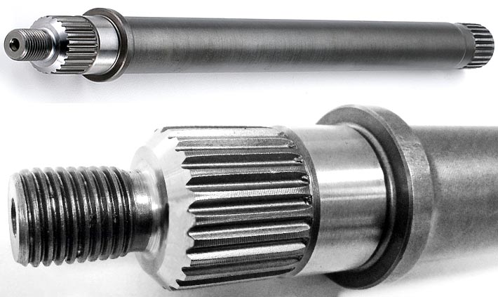
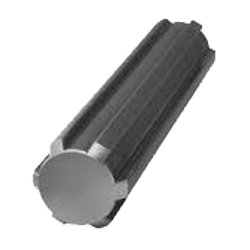
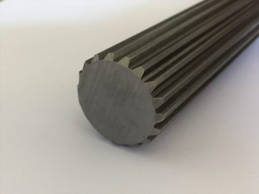
A spline shaft features a series of ridges or teeth (splines) that are machined onto its surface. These splines create a precise and controlled interface with mating components, allowing for torque transmission and relative movement. In contrast, other types of shafts, such as plain shafts or keyed shafts, do not have the splines and rely on different mechanisms for torque transmission.
2. Torque Transmission and Relative Movement:
Unlike plain shafts or keyed shafts, which transmit torque through a frictional or mechanical connection, spline shafts allow for both torque transmission and relative movement between the shaft and mating components. The splines on the shaft engage with corresponding splines on the mating component, creating an interlock that transfers rotational force while accommodating axial or radial displacement. This feature provides flexibility and is particularly useful in applications where misalignment or relative movement needs to be accommodated.
3. Load Distribution:
One of the advantages of spline shafts is their ability to distribute loads over a larger surface area. The multiple contact points created by the splines help distribute the applied load evenly along the shaft’s length. This load distribution minimizes stress concentrations and reduces the risk of premature wear or failure. In contrast, other types of shafts may rely on a single keyway or frictional contact, which can result in higher stress concentrations and limited load distribution.
4. Design Flexibility:
Spline shafts offer greater design flexibility compared to other types of shafts. The number, size, and shape of the splines can be customized to meet specific design requirements. This allows for optimization of torque transmission, load-bearing capacity, and relative movement characteristics based on the application’s needs. Other types of shafts may have more standardized designs and limited customization options.
5. Application Variability:
Spline shafts find widespread use in various industries and applications where torque transmission, relative movement, and load distribution are crucial. They are commonly employed in gearboxes, power transmission systems, steering mechanisms, and other rotational systems. Other types of shafts, such as plain shafts or keyed shafts, may be more suitable for applications that require simpler torque transmission without the need for relative movement.
6. Installation and Maintenance:
When compared to other types of shafts, spline shafts may require more precise machining and alignment during installation. The mating components must be accurately matched to ensure proper engagement and torque transfer. Additionally, spline shafts may require periodic inspection and maintenance to ensure the integrity of the splines and optimal performance.
In summary, spline shafts differ from other types of shafts due to their spline structure, ability to accommodate relative movement, load distribution capability, design flexibility, application variability, and specific installation and maintenance requirements. These characteristics make spline shafts well-suited for applications that demand precise torque transmission, flexibility, and load distribution.
editor by CX 2024-02-03


